Claster Automation Set is a collection of three devices designed to control electrical circuits by executing commands received over a network.
The system’s advantage lies in its reliability and versatility. It can be integrated with virtually any other automation device currently available on the market. Examples include the Raspberry Pi, Beaglebone, Loxone, KNX, Siemens Logo, and any other devices capable of supporting internet protocols.

The kit contains:
- Claster 24V Power Supply
- Claster Universal Switch
- Claster Universal Dimmer
How To Setup
- Place the controller along with the power supply in its designated location.
- Connect 24v power supply to controller – orange LED and red LED will turn on.
- Connect the controller to the LAN using the ethernet cable.
The device will automatically assign itself an IP address. If successful red LED will turn off.
Now system is fully functional.
Configuration
- To obtain an IP address, log into the web interface of your home router. This typically involves opening a web browser and entering your router’s IP address (commonly 192.168.1.1 or 192.168.0.1). Once logged in, you can view the assigned IP addresses for connected devices on your network.
- All other necessary information about your device can be found on the label located at the side.
- Configuration doesn’t require any programming knowledge, as installation instructions with pre-made templates for various systems will be available in download section.
Mode.1
This mode is the first of two fundamental modes, offering the capability to function as an extension to an existing system. It allows for issuing commands over the network while simultaneously controlling all circuits directly using digital inputs. This ensures that basic functionality is maintained even if the control device fails or is disconnected. The mode is designed to work with momentary switches.

Mode.2
This mode is the second of the two fundamental modes and also has the capability to function as an extension to an existing system. Similar to Mode 1, it allows for issuing commands over the network and direct control of all circuits using digital inputs, ensuring maintenance of basic functionality in case the control device fails or is disconnected. However, this mode is tailored for use with latching switches.

Extent
This mode represents a full extension of the system. Unlike the previous modes, it does not allow for direct control of circuits using digital inputs. Instead, all information received, whether from digital or analog inputs, is directly forwarded to the controlling device. This mode is versatile and designed to work with switches of any type.

UDP COMMAND LIST
| Command | Function | Direction | Example – Effect |
|---|---|---|---|
| A0…A100 | Dimmer 1 power 0%…100% | Received by CLS | A100 – Switch ON dimmer 1 to full power |
| B0…B100 | Dimmer 2 power 0%…100% | Received by CLS | B0 – Turns dimmer 1 OFF |
| C0…C100 | Dimmer 3 power 0%…100% | Received by CLS | C25 – Sets dimmer 1 to 25% |
| D0…D100 | Dimmer 4 power 0%…100% | Received by CLS | D80 – Sets dimmer 1 to 80% |
| E0 – E1 | Relay 1 OFF – ON | Received by CLS | E1 – Turns realay 1 ON |
| F0 – F1 | Relay 2 OFF – ON | Received by CLS | F0 – Turns relay 2 OFF |
| G0 – G1 | Relay 3 OFF – ON | Received by CLS | G1 – Turns realay 3 ON |
| H0 – H1 | Relay 4 OFF – ON | Received by CLS | H0 – Turns relay 4 OFF |
| I0 – I1 | Digital input 1 signal LOW – HIGH | Sended by CLS | I0 – If digital 1 signal LOW |
| J0 – J1 | Digital input 2 signal LOW – HIGH | Sended by CLS | J1 – If digital 2 signal HIGH |
| K0 – K1 | Digital input 3 signal LOW – HIGH | Sended by CLS | K0 – If digital 3 signal LOW |
| L0 – L1 | Digital input 4 signal LOW – HIGH | Sended by CLS | L1 – If digital 4 signal HIGH |
| M0 – M1 | Digital input 5 signal LOW – HIGH | Sended by CLS | M0 – If digital 5 signal LOW |
| N0 – N1 | Digital input 6 signal LOW – HIGH | Sended by CLS | N1 -If digital 6 signal HIGH |
| O0 – O1 | Digital input 7 signal LOW – HIGH | Sended by CLS | O0 – If digital 7 signal LOW |
| U0 – U1 | Digital input 8 signal LOW – HIGH | Sended by CLS | U1 – If digital 8 signal HIGH |
| P0…P100 | Analog input 1 signal 0% – 100% | Sended by CLS | P0 – If analog 1 signal 0% (LOW) |
| R0…R100 | Analog input 2 signal 0% – 100% | Sended by CLS | R25 – If analog 2 signal 25% |
| S0…S100 | Analog input 3 signal 0% – 100% | Sended by CLS | S80 – If analog 3 signal 80% |
| T0…T100 | Analog input 4 signal 0% – 100% | Sended by CLS | S100 – If analog 4 signal 100% (HIGH) |
| U | All dimmers and relays status | Sended and Recived | Returns all channels values for status verification |
| W | All digital and analog values | Sended and Recived | Returns all inputs values for status verification |
| X | Hardware and firmware versions | Sended and Recived | Returns system info for updates |
| Y | Reserved | – | – |
| Z | Reserved | – | – |


Switch Specification


Futures
- 8x Actuators AC/DC (Normally Open/Normally Closed)
- Max Current for Channel: 13 Amp
- 8x 24V Digital Inputs
- 4x 24V Analog Inputs
- 1x USB
- 1x LAN
- Communication Type: User Datagram Protocol (UDP)
- Weight: 350g
- Material: ABS
Dimmer Specification
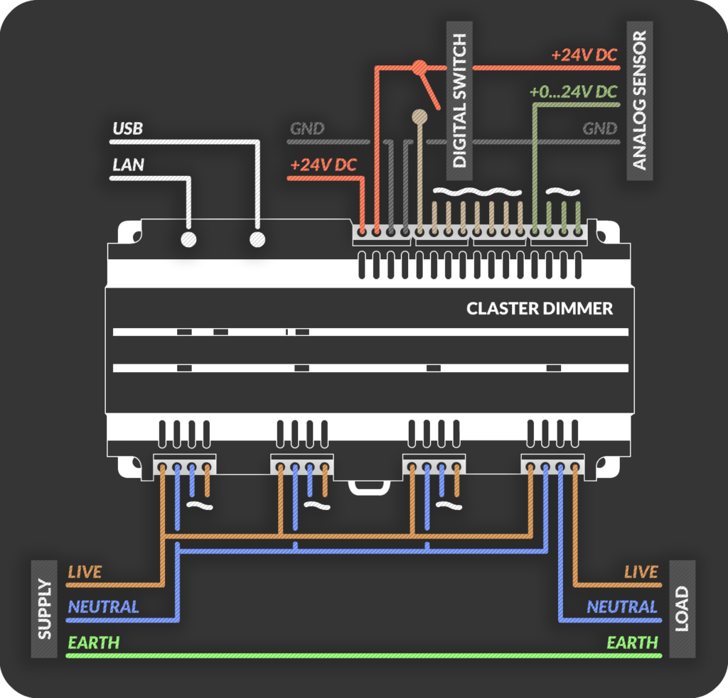
Futures
- 4x AC Dimmer
- Max Wattage for Channel: 500W
- Dimmer Type: Trailing Edge
- 8x 24V Digital Inputs
- 4x 24V Analog Inputs
- 1x USB
- 1x LAN
- Communication Type: User Datagram Protocol (UDP)
- Weight: 380g
- Material: ABS
Should you require further information or assistance, please do not hesitate to contact us.
PROMOTIONAL VIDEO


Q and A
You haven't found answer to your question related to this product?
We will provide an answer to your question and display it in this section so that there’s no need for anyone to ask it again.